Quartermaster’s report and current projects after AGM 23rd May 2025
This report would have been presented at our AGM a few days ago but since everyone who actually turns up knows what is going on there was no need. It is presented here for everyone else.
As I am also acting Treasurer I am able to say that the Club’s Magic Hat financial policy (a Glastonbury tradition) seems to have been working well as having over the past year found ourselves able to afford to undertake a number of desirable technical projects we have done so.
These projects include (but, as the legal phrase has it, ‘are not limited to’) the restoration of a twelve-metre (40ft) telescopic, transportable lattice tower, the construction of a rotating HF beam to work on this tower and the research and development of a satellite earth station, and are covered separately at the end of this report.
Scout Hut
Following the death of G5FM and the retirement of 2E0RWW our arrangements with the Scout Organisation have lapsed, though the Scout Hut remains our registered address for exam purposes - however given the withdrawal of paper exams by the RSGB it will not henceforth be required.
The Club would like to thank the Scout Organisation for its patience and hospitality over the years and would be happy at any time to poach any of its members who show any interest in radio.
Club site
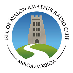
There was some concern expressed earlier this year when the field next door to ours was occupied by a group of what might be called alternative campers.
However it soon emerged that these are the harmless hippie kind and that they appear to have the blessing of the council, to whom the land belongs. We have not bothered them, and they have not bothered us.
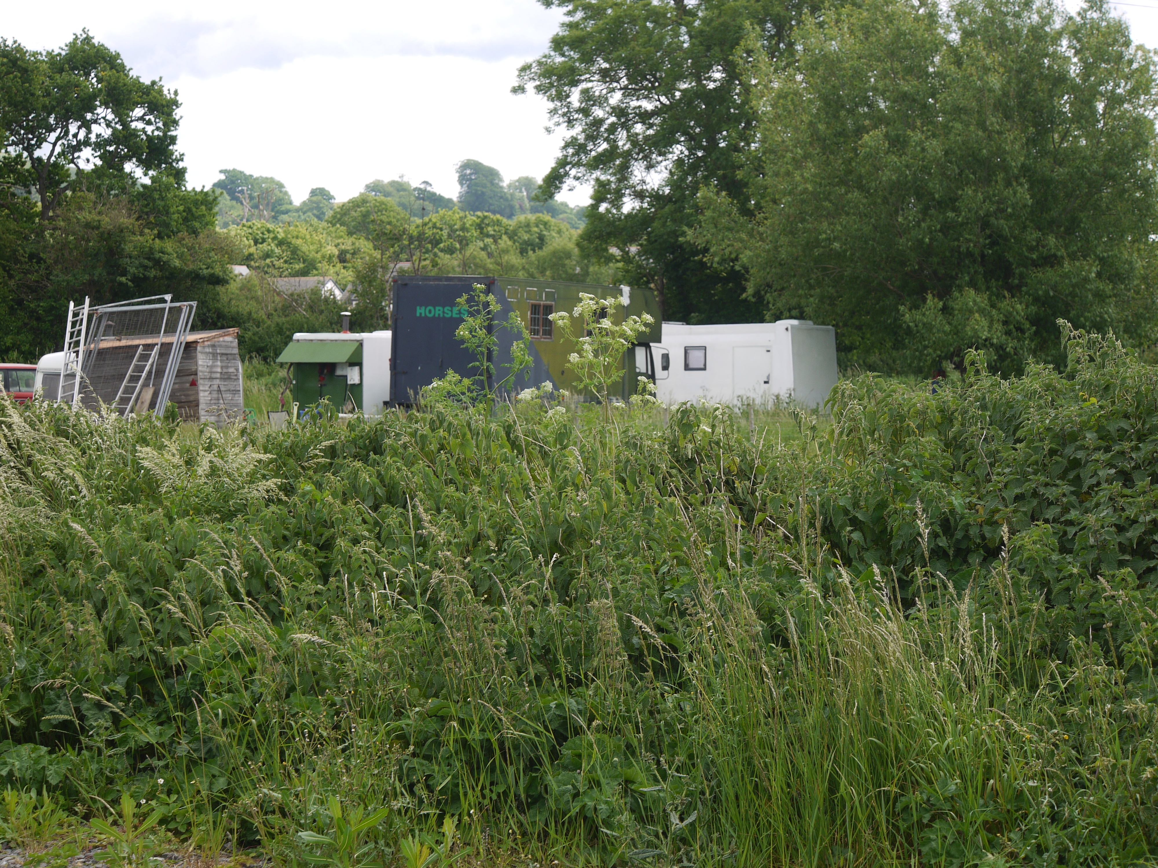
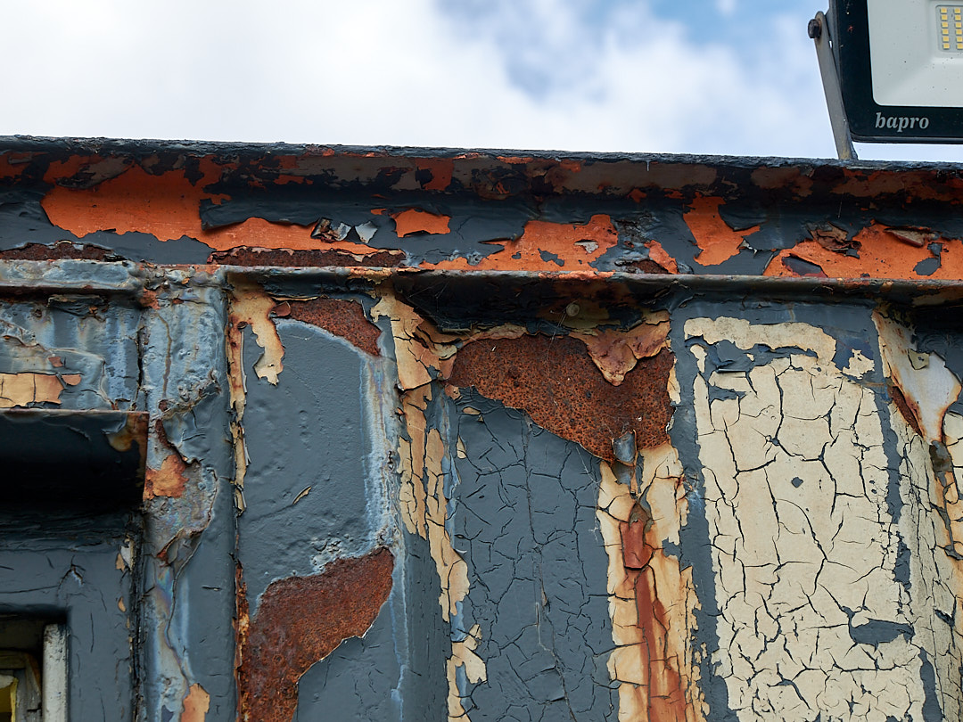
Of more concern is the condition of the hut, which being steel is rusty. When weather and other circumstances permit this will have to be addressed. The separate storage container is in better condition and can wait its turn.
We no longer have any sanitary facilities, the toilet tent having departed from the site during a gale (it was never found). It may be possible to make an arrangement with the caravan site nearby which would allow the use of caravan-type equipment.
Attempts are being made to obtain suitable furniture (e.g. we need an office type stationery cupboard of the traditional kind, if anyone out there has such a thing going begging) to allow rearrangement of the hut into three areas: shack, lounge and kitchen, with a view to providing the shack with screen space, more effective lighting and a quieter environment for operating.
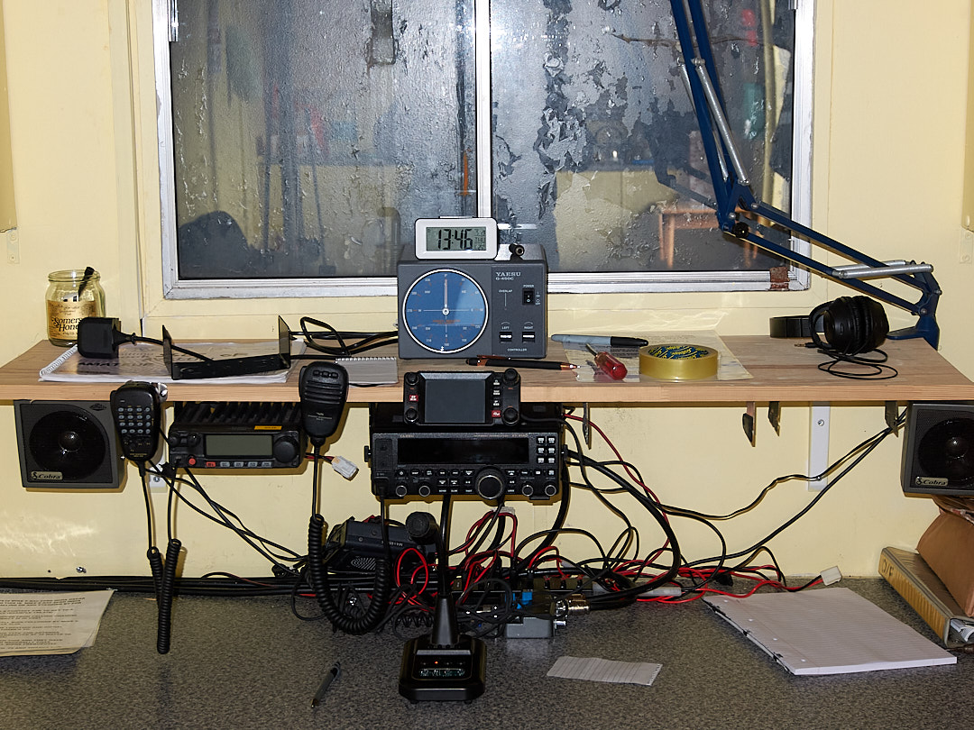
The shack itself is showing signs of age and is not arranged as conveniently as it might be for new equipment such as patchbays so this too will soon have to be looked into.
Radio equipment
There has been no change in the HF provision as our FT-450 provides enough power for Blue Ham and is now a sought-after classic. We expect the new HF beam and tower to make a great difference to everyday working but will continue to maintain the 1:1 long wire for bands not covered by the beam and also the 60m dipole currently used exclusively for Blue Ham.
All six of the Club’s Baofeng UV-5R 2m/70cm FM handhelds have been upgraded with Nagoya 771 type antennas (nos. 1-4), tape-measure ‘tactical’ type antenna (no.5) or telescopic trapped whip (no.6) with a view to comparing different kinds of aftermarket antenna for this very popular rig.
Patchbays for receivers (BNC) and transmitters (N) are being designed with a view to minimising the wear and risk of damage to the sockets on the backs of rigs when connecting and disconnecting heavy coaxial cables. The loss and SWR change associated with patchbay bulkhead connectors though not insignificant must be offset against the risk of serious rig damage (if a socket is so badly damaged as to go open circuit the rig output stage could blow).
Current projects
Trailer-mounted lattice tower
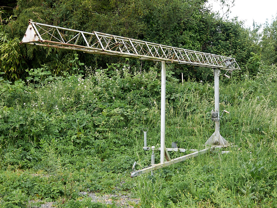
This tower was obtained ‘for a song’ (albeit adequately accompanied) some years ago and has since been awaiting restoration. Though it looks very like a Versatower it seems not to be one of those but a rather less pretentious make. Its history is peculiar: it was, we were told, made by some radio amateurs out of a salvaged fixed-base tower and a trailer originally made for a boat. It is road legal and has the usual trailer equipment.
A previous attempt at restoration of the tower’s lifting and luffing gear lasted only briefly as it was found that the supplied stainless steel winch cables aged very rapidly and were soon condemned as unsafe by engineering Members.
As if to confirm this judgement the luffing cable subsequently broke near the winch upon testing. As maximum stress in this cable occurs immediately after the tower lifts off its cradle it failed quite safely at this point, the tower falling a matter of millimetres back into the cradle.
As the tower is made of steel it is rusty. We hope to deal with this by stripping and repainting the whole structure. So far only the very topmost part, the tetrahedral rotator frame, has been restored.
Prior to restoration it was found necessary to offer up this top section to the fittings on the tower and to straighten all of the studs by which it is fastened to it. One of these studs had been badly damaged and was kindly replaced gratis by a welder friend of G6UVO’s next door neighbour - thanks, Andy!
Once the top section’s corrected fit had been tested it was dismantled and cleaned for painting. The bottom plate, already drilled for an earlier rotator, was drilled again for the new and larger Yaesu G-450C type selected for this job.
Normally a thrust bearing would be used to transfer all of the weight of the antenna system from the rotator’s shaft to the tower, leaving the rotator to turn the array without having to support it. A Yaesu GS-050 thrust bearing was duly obtained but despite days of filing, fettling and making special parts it was found impossible to make it fit without its either dragging the rotating shaft or wobbling up and down like the swash-plate of an helicopter.
Calculation had shown that the expected head load, thanks to the very lightweight antenna, would be only about 11% of the rotator’s design limit anyway and so the thrust bearing was abandoned - it will probably be used to make one of the omnidirectional antenna masts rotate to provide another beam mount.
The tower’s original top bearing was drilled and tapped for grease nipples, which are fitted so that when the tower is stowed they can be serviced from beneath without having to climb.
Having removed loose rust and original primer the top section was primed with a single unthinned coat of Guard GIP high performance red oxide primer and finished in Montana 94 (a brand of aerosol paint sold for street art but found to be very cost-effective elsewhere) Maya Green, which from the Airfix point of view looks rather like the olive green used by the US Army Air Force in WWII. The late G5FM, a lifelong pacifist, despised this ‘militaristic’ colour, calling it ‘Goose Shit Green’. We all hope and expect that where he is now the decor is in better taste but feel it prudent to make every effort to have our apparatus blend into its background rather than being an ‘eyesore’.
Further progress on this project will if all goes well be reported rather more as it happens than has been the case hitherto.
HF beam antenna
To avoid the numerous logistical complexities associated with large 3-element Yagi antennas for HF made from alloy tubing we have elected to use a fibreglass-and-wire Yagi type, a Spiderbeam 5 HD, which though 10m across weighs only 7.5kg (and this is the ‘heavy duty’ version for permanent installation - the portable version weighs only 6kg).
Many antennas are for convenience sold in ‘knockdown’ or ‘self-assembly furniture’ form with several components which fit together to be fastened with screws or whatever. This one however is in genuine ‘kit form’, consisting of a bundle of tubing, two alloy plates, several reels of wire, a bag of bits and some rather detailed instructions.
We hope to make building this antenna an event for the Club but this cannot happen until the lattice tower is ready to receive the completed antenna, as there would be nowhere else to put it and it would fill up the car park.
Tilt plate
Geometers among our readers will have noticed that tilting over a c.6m (lowered; 12m when raised) tower with a 5m turning radius antenna on it will result in the antenna striking the ground when the tower is only about halfway down (calculation of the fatal angle is left as an exercise for the student 1).
This being a common problem there is a prescribed solution to it called a tilt plate, which is a form of hinge allowing the antenna to tilt as the tower luffs down, ending up (in our case) stowed on top of the tower and parallel to it.
Tilt plates are available commercially but the only British one, though clearly strong enough and only (“only”) £175, does not allow remote control, the user having to insert or remove a safety-clipped pin to secure the plate in one of its two positions, having perhaps ascended a stepladder or similar in order to do so.
US suppliers offer much more impressive tilt plates, enormously strong, with axles and Plummer blocks rather than mere pivot-bolts, but even these have to be amateur modified to provide remote control and the cheapest one found was $750.
Either of these commercial solutions could be seen as overkill given that the Spiderbeam antenna weighs only 7.5kg and some of the larger American tilt plates are able to support almost half a ton.
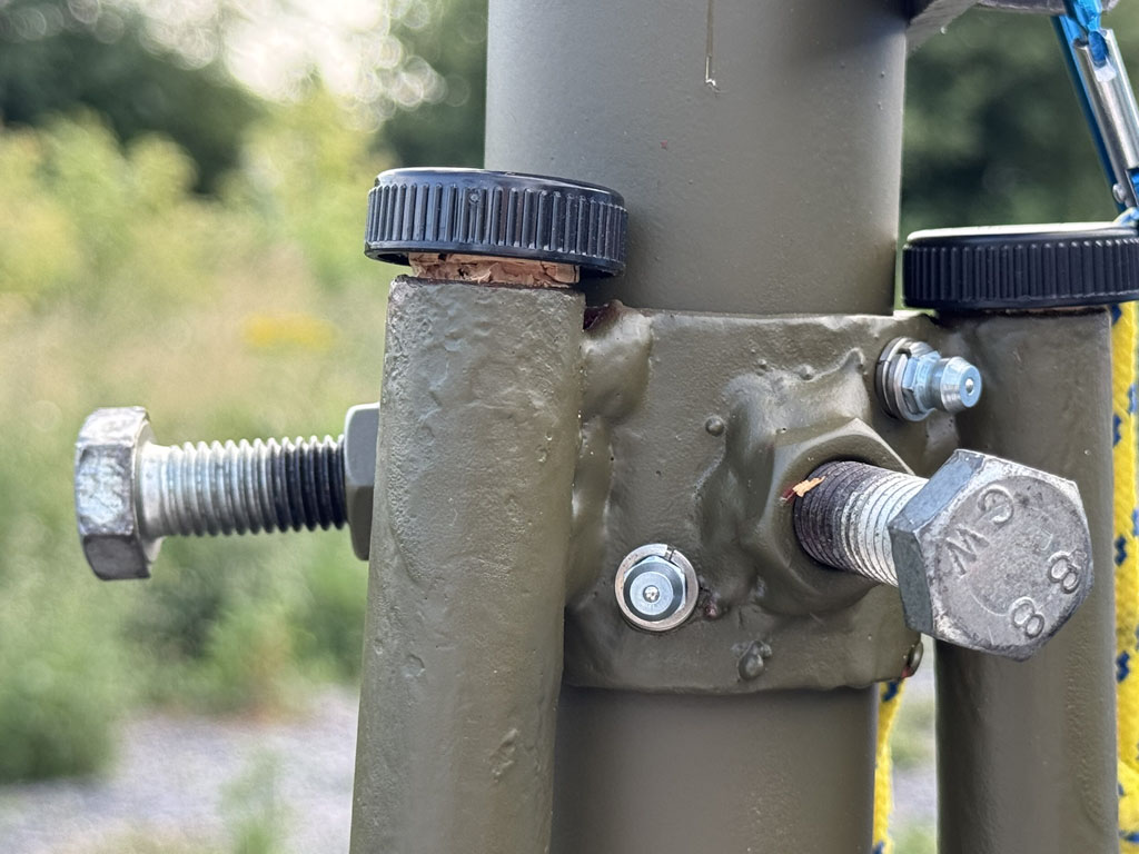
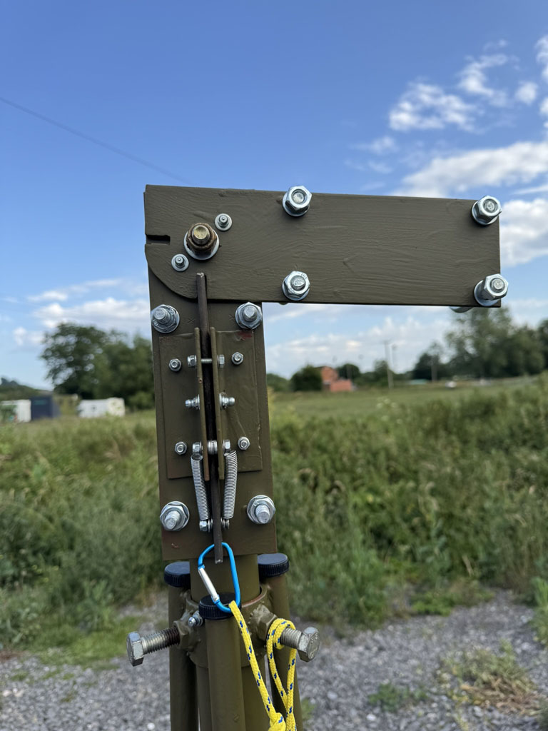
Accordingly a tilt plate of the simplest pivot-bolt kind, but with a cord or pole operated locking bolt, was designed and made from scrap steel plate and angle iron in Club workshops. It weighs 2.75kg. The rotator shaft having been cut to a suitable length this device has been attached to it, ready to receive the shaft remnant on which the HF beam antenna will be built.
Satellite earth station
In 1974 an amateur radio satellite called AMSAT-OSCAR 7 (‘Amateur Satellite Organisation’, ‘Orbiting Satellite Carrying Amateur Radio’) was launched. In 1981 it ceased operating, but in 2002 mysteriously came back to life, albeit intermittently. It is the oldest operational satellite in the world, and was once used to help develop the COSPAS/SARSAT satellite rescue system which is now taken for granted worldwide.
It was suggested by G6UVO, who is a member of AMSAT-UK, that the Club attempt to work this historic satellite while it is still available.
Modern satellites are in many cases easy to work with minimal equipment but the traditional kind requires a full earth station consisting of antennas capable of being aimed at any part of the sky, a computer to predict the positions of satellites and to move the antennas to track them, and radio equipment capable of dynamic adjustment to compensate for the Doppler effect upon both uplink and downlink frequencies. More information on amateur satellite work here.
AMSAT-OSCAR 7 Mode A downlinks on 10m for which the traditional antenna is a rotary dipole. It may be possible to use the new HF beam in this role and so no dedicated dipole is currently planned.
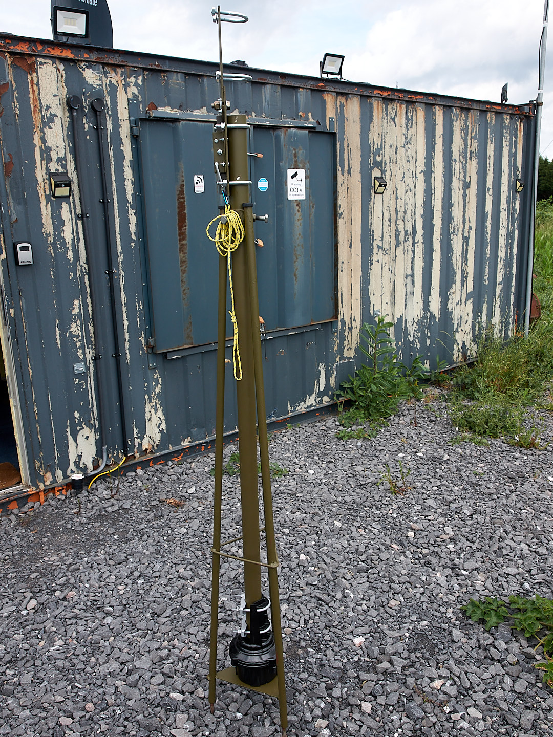
The array under construction now is a traditional phased-Yagi pair for each band with remote selection of RHCP or LHCP by means of a phasing line switched between dipoles by a coaxial relay. General-purpose antennas allow the array also to be used for terrestrial work.
The mount consists of a Yaesu G-5500 rotator fitted to a 6m fibreglass pole mast, a 3m section of the same tubing providing the crossbar on which are fitted in 45/135 degree orientation (giving symmetrical windloading) a pair of Diamond A144S10s for 2m and another of A430S15s for 70cm, phasing gear being contained in a sealed box attached to the rotator set.
Fully automatic operation is hoped to be achieved by feeding control data to the rotator control unit via an AMSAT type USB interface from a Windows laptop running SATPC32 and also sending CAT data to an FT-991 rig which will apply the Doppler corrections.
-
one must allow for the height above ground of the tower luffing hinge which is about 1.5m ↩