SAQ Grimeton 50th UNESCO anniversary transmission received on 17.2kHz
SAQ is a lovely old non-electronic transmitter - a 200kW alternator directly generating the RF signal at 17.2kHz - the CW is modulated using a magnetic amplifier. More about this transmission at SAQ. I have tried and failed to receive this signal a couple of times. It’s a tough signal to optimise, because you only get a couple of chances to line up in a year. I had a previous go in June but SAQ were unable to run the transmitter. It’s not something you can really tweak in real time. I don’t copy Morse, so I used FLDigi on this. I don’t really know why FLDigi did such a rotten job, as I’d put the signal at about 448 but that’s machine morse decoding for you. There’s something quaint about what sounds like chirp on the signal

CQ CQ DE SAQ SAQ SAQ
65 GRIMETON RADIO STATIONUQ IN A TÈ6MSSION USING T5 AAANB*ON 200 KW ALNRXTOR ON 17.2 KHZ. T 16TH OF NOVEMBER 2022 MAR* 6E 50TH ANNIVE*ARY OF THE WORHERITAGE CONVET2N. UDSWOD HE TAZ 5TES AL IUÇAB A*ETS OF HUMANITY BUT MANY OF THEM * 6LTNNL TODAY TH*UGH UNNTROLLED URBABZADON, UNCECKEDTOURISM, ARMED CONFLICT AND CLIMATE CHANGE. TO ENSUL THEIR PROTECTION,INTERNATIONAL COOPERATION TO PROMOTE PEACE, IKE\WIONAL UNBRSTANDING AND SUSTAIXB DEVELOPMENT 5 MORE IMPORTANT 6AN EVER. 5NL: LEX SOMMEST*, CHLR SWEDISH XT2N* MISSION FOR U*CO, WORLD HUITAZ G METON RADIO STADON PD T5 *EXANDER-GRIMETON FRIENDSHIP ASSOCIATDON. E FOR QINFO PH READ OUR WEBSITE: WWW.ALEXANDER.N.SE DE SAQ SAQ
An 8kHz sampled copy of the audio signal
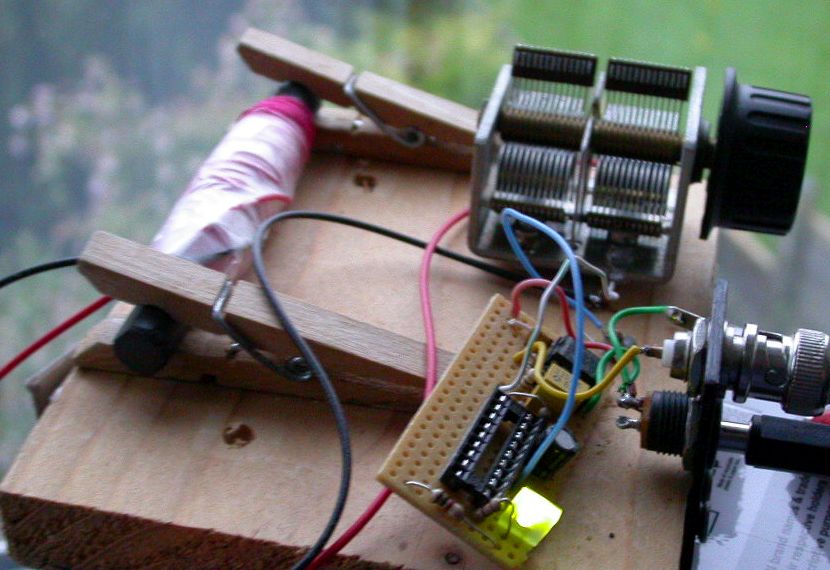
17.2kHz needs a massive antenna on the transmit side. The receiver, however, gets away with a ferrite rod. I’m not particularly proud of the standard of construction, but it did the job, this time using a CA3140 opamp

I use a green LED as a voltage reference diode to bias the coil about 2V off the negative rail, and to see when power is applied. Gain is about 20, bias is applied straight through the coil, with the 2V decoupled to ground at the cold end of the coil with C1. R5 stands off the output cable a bit, and C4 blocks DC. A 9V battery feeds in through the barrel jack, 6-12V is fine. C5 decouples the power supply and should be near the CA3140. The CA3140 is a MOSFET device and has an input capacitance of 40pF and a very high Zin, the capacitance is typically swamped by C2 and the parasitic capacitance of L1. Making L1 is cut and try, you want about 0.28H with a typical AM broadcast variable paralleled. I was prepared to shunt caps across it using the IC socket if necessary, but it wasn’t.
Do not simply substitute the CA3140 without some reflection on input and output common-mode range. The CA3140 goes down to 0V on input and output common-mode is within 3V of V+. Hence the oddball DC bias at ~1.9V (for a green LED). Something like a TL071 doesn’t go all the way to 0V in or out and is marginal biased mid-rail with a 9V battery, particularly a cheap rechargeable which are often 7.2V.

Software used - this is outlined in the previous attempt


Below is the SAQ video of the alternator being started and the transmission
