80m VFO for intermediate practical training
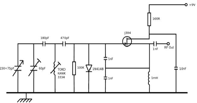
The Amateur Radio training syllabus requires a VFO, for trainees to calibrate by finding the band edges. I chose 80m for this - there is a standard circuit used which uses a Toko KANK3334 coil which is obsolete and pretty unobtainium these days. There’s also the issue of frequency stability - ferrite material in your VFO coil is bad news because it introduces more temperature dependency, and that is the enemy of stability. So I wanted an air-cored coil. A look at the standard circuit shows a FET Colpitts oscillator. I also didn’t really care for the 1mH RF Choke, because I don’t have one to hand.

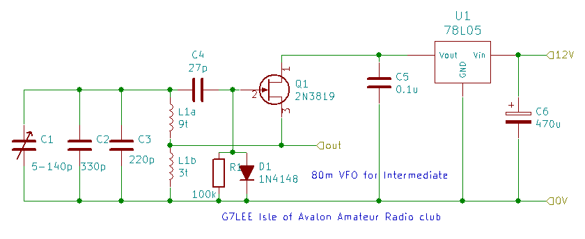
However, the tapped capacitor arrangement can be swapped for a tapped inductor approach to get a Hartley configuration as done by K0JD - you tap the inductor in a ratio about 75% to 25% with the 25% end to the earthy side. I used a former made of 20mm plastic electrical conduit. Polystyrene cement is used to mechanically stabilise the coil on the former. In a real VFO I’d probably prefer a ceramic former but this will do. I constructed this from some pieces of copper-clad board a bit along the lines of M0HTA

This works fine for calibrating the band edges, it is stable enough over a training session. Our main problem was finding a large enough graduated knob to let people set this accurately enough and be able to read where they are. The fixed capacitors pad the range of the variable capacitor so that it covers just over the 80m band. A bandspread trimmer of about 20pF has been added to show how fine control can be done.
D1 prevents the gate going more than a diode drop positive with respect to the source, which would forward bias the gate-source junction. The data sheet allows for a maximum forward gate current of 10mA before damage to the 2N3819 occurs.
There is an argument that modern practice will tend to use varicap diodes, which may give greater temperature stability than the air spaced capacitor whose dimensions will vary with temperature. Varicaps are a lot cheaper. But I had the capacitor, and for a teaching item the air-spaced variable is a component that wears its heart on its sleeve - it is obviously a pair of parallel plates and a dielectric, in an obvious way that a reverse-biased diode junction just isn’t.
2020-01 update - this practical has been extended with the new Intermediate syllabus to compare the frequency stability of the VFO with a crystal oscillator
